The Tamesis Trust

First report on the examination of Cygnet

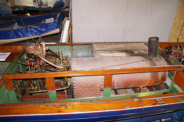
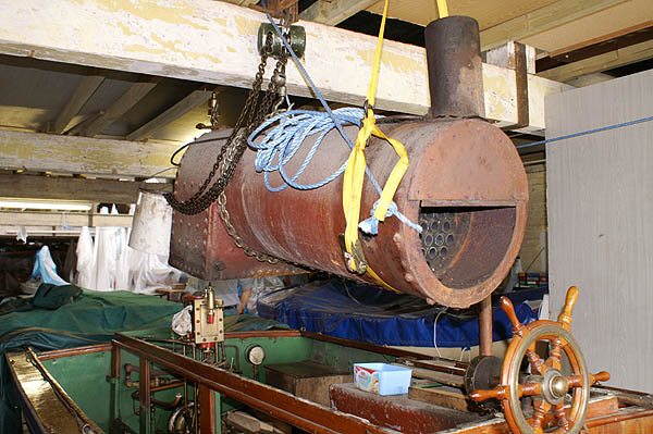
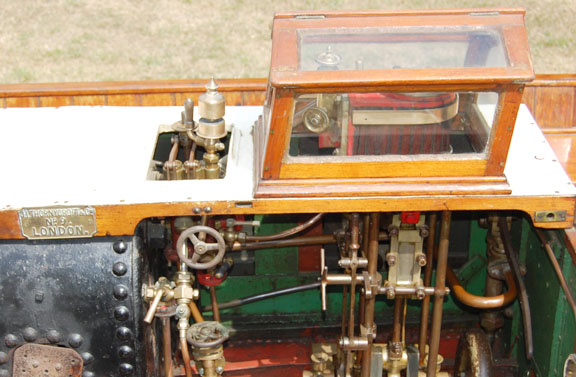
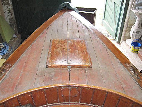
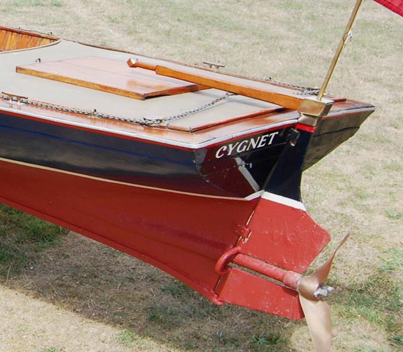
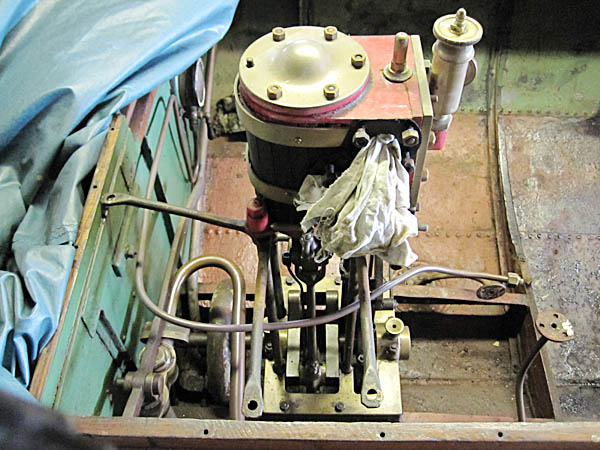
Cygnet is a 29ft long steel hull steam launch built by J.I. Thornycroft in 1870


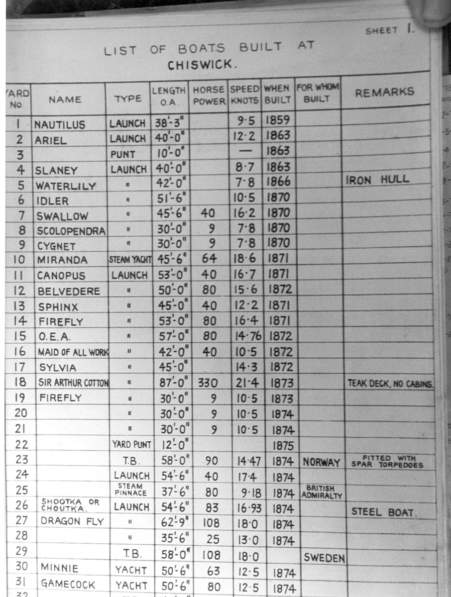
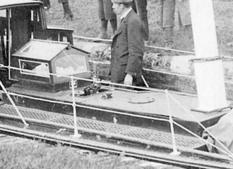
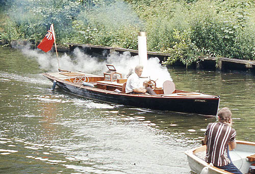
Cygnet in steam at  Steamboat Rally based at Datchet in 1970 Thornycroft's list of boats, Cygnet is No.9

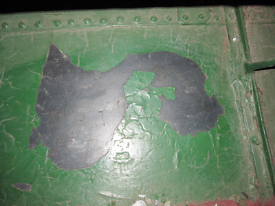
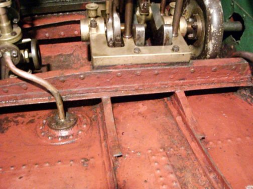
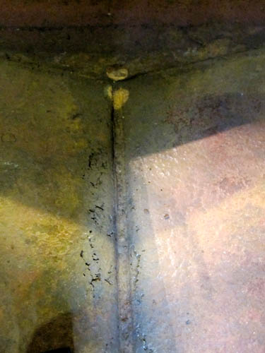
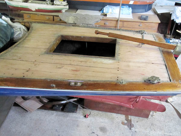
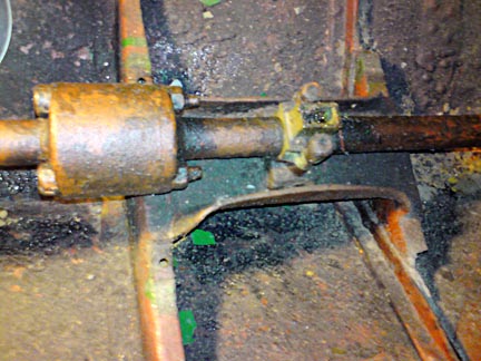
Work has started to assess the condition and prepare Cygnet ready for public display. The examination has revealed many details of the construction techniques used by Thornycroft during the early years of this important shipbuilder's business

Our first task was to remove the boiler and clean out the debris and rubbish in the bilges.

The Boiler

The exterior condition of Cygnet's locomotive style boiler is very good, however it has been difficult to see the inside surfaces except through some rather small holes.

There is no steam dome, so steam is taken via a piccolo tube to a complex bronze casting which houses the twin Salters type safety valves, the engine throttle, and the steam supplies for blower, bilge ejector steam injector and pressure gauge. The side fired boiler has 5/16" plate and is of flanged and riveted construction, with a 16" diameter barrel, fitted with 39 off 1¼" brass fire tubes. This boiler is a replacement probably of the late 1890's or 1900's.

Steam take off via a manifold on the backhead seems to have been a feature of early launches built by Thornycroft.

Cygnet's boiler is quite long - the smokebox is a continuation of the boiler barrel. Note the steam take off manifold on boiler backhead.

The boiler probably weights a quarter of a ton.

The front steering wheel is a rather crude later day modification

Cygnet boiler top opening showing safety valve and whistle

Eva in the 1890's showing similar safety valve and whistle arrangement

The Hull - riveted blued steel sheet

Our examination of the hull has revealed that the original plating is blued steel sheet about 16swg thick which was painted with a Brunswick green non gloss leaded paint. Note there were no gloss paints at this time. There is a keel, probably of iron about 1/2" thick, and the hull plates at the garboard are bent down to be riveted through this keel. Some of the bottom plates under the boiler and the forward compartment have been replaced but are now badly corroded. The plating under the engine is original and still in good condition.

Hull plating here is in good condition, the blue colour is not paint but a stable oxide of steel providing a protective finish - blued steel The plating here under the engine is original and coated in red lead, probably also protected by oil from the engine. note water intake pipe to injector. These replacement plates in the bow are now rotted through.

For and aft decks

These decks were covered with linoleum believed to have been fitted in the 1960's and in need of replacement. On removal we were surprised to find a fine laid teak deck with caulked seams paid with pitch. The planks are wide and each plank has one central groove also filled with pitch to simulate the effect of narrower planking. At some time in the past this was covered by canvas or linoleum, presumably to reduce maintenance and make leak proof.

Fore deck. The covering boards have no fixings from the top, but are secured to the hull plating at the side and from screws through brackets beneath Aft deck. There are floor boards in the aft compartment and it is thought that the helmsman could sit here by the tiller. The wheel steering was added later.

Steering

The 1873 GA drawing obtained from the National Maritime Museum for Thornycroft No 8 (Scolopendra) and 9 (Cygnet) does not show the present steering wheel as fitted in the fore compartment. This drawing shows a nice curve shaped tiller. The assumption is that drawing was produced for the construction of another five launches of this size built over the next six years.

It is likely that steering was either by a person who sat at the small aft compartment or by ropes looped through sheaves to a steers person in the aft compartment, which would be similar to the steering of rowing skiffs of the period. The bow steering wheel arrangement is a rather rough addition and there are several detail clues which show that it was probably a later day addition.

Section of 1873 GA drawing;  note nice curved tiller arm

The twin rudder blades have clearly been extended

The split rudder is fitted in front of the propeller and this was a common feature of powered boats of the time. The theory was that the propeller needed to work in undisturbed water away from the hull for best efficiency. This does however make the rudder less responsive at very slow speed;  so it seems that the rudder blade area has been increased from that shown on the 1873 drawing presumably to improve matters.

There is a spacer fitted to a coupling joint on the propshaft, we presume this was to move the propeller position further back to allow room for the rudder extension. Note wick type oil box on the shaft, prop thrust on Cygnet is taken by an enlarged main engine bearing.

The Boiler feed arrangements - The Gifford Injector

This is a Gresham Gifford type injector. The principle of the Injector was patented by Henri Giffard in 1858 and Gresham was one of several engineering companies who started to make them in the late1860's. The top valve is the steam control and the side wheel is the water control.

This hand pump is fitted to Cygnet but would only be used in an emergency. The pump would take a lot of effort to keep the boiler water level up while running the engine, something like 20/30 gallons of water per hour would be required.

This advert for the Gresham's patent injector is from about 1874 and shows an injector which looks identical to the one in Cygnet.

Gifford sent a sample of his injectors to several engineering companies:- Gresham, Stephenson, and Sellers. Greysham carried out some improvements, the main one seems to have been the use of adjustable combination cones, which was patented in 1865. This model of injector was still available in the late 1930's.

The smallest size (1/2" Cygnet size) was then priced at 80 shillings, delivery claimed as 180 gallons per hour.

The engine

The engine is 3¾ inch bore by 5 inch stroke double acting single cylinder with Stephenson link reverse gear on a slide valve. The cylinder is cast iron and the engine has four very thin vertical steel columns mounted on a bronze bed plate. The engine was rated at 9 HP at 700 rpm using steam of 76psi. The horse power output of later models of this engine design was uprated by Thornycroft to about 13 HP using higher revs and working pressures of 120 psi. The engine was operated non condensing giving Cygnet a speed of 7.8 knots.

There are three stabilising bars on the engine cylinder which are bolted to the steel boiler top (seen in photo on the right). These were needed to stiffen the engine because of the light unstayed columns used to support the cylinder assembly.

Conservation work

The conservation work carried out so far has been to clean out all the rubbish in the bilges and treat the whole of the inside hull bottom area with a rust inhibitor, then painted internally with Red Lead to the water line and Brunswick green (non gloss) to the decking. The floorboards have been repainted with a grey matte paint matching the original colour. The fore and aft decking have been restored to their original build state (scrubbed teak with pitch caulked seams). The boiler has been cleaned externally and repainted with read lead then finished with a matt black paint.

All brass and copper has been lightly cleaned.

No work has yet been carried out on the hull exterior.

More to follow shortly

Technical details    or   Home page